Most trailing-cable failures on mobile mining equipment are mechanical before they are electrical. A jacket is cut on a rock rib, a cable is run over at a haul-road crossing, or a grounding conductor breaks inside an intact jacket. The last one is the failure a crew cannot see, and it is the reason the 2 kV Type G-GC construction carries a separate ground-check conductor next to its two grounding conductors.
What a trailing cable goes through
A trailing cable on a continuous miner, shuttle car, blast-hole drill or dewatering pump is a moving part, and the moving does the damage. Abrasion opens the jacket: a general-purpose PVC-jacketed cable gouges on sharp rock, and once it is open, mine water reaches the insulated cores. Crushing by a tire or a fall of rock leaves a thermoplastic jacket flat; a thermoset elastomer recovers its shape. If pulling force reaches the copper, strands neck down and break and the smaller cross-section runs hot, which is what the textile reinforcement under the jacket is there to prevent. Underground the jacket also sits in acidic water and hydraulic oil; on a surface bench it sits in sun and ozone, and ambient temperature sets how much current the cable can carry.
The hazard that does not show on the outside is a grounding conductor broken under an undamaged jacket. The machine keeps running until an insulation fault puts phase voltage on the frame. In practice it happens at the machine entry and at the coupler, where the cable is bent, pulled and clamped at the same time.
How a round 2 kV Type G-GC cable is built
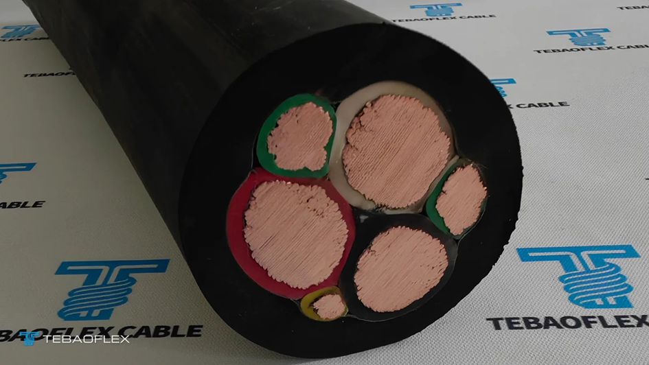
The construction is defined in ICEA S-75-381 / NEMA WC 58, the North American standard for portable and power feeder cables used in mines: three power conductors, two grounding conductors in two of the interstices, and one insulated ground-check conductor in the third. The published datasheet for TEBAOFLEX’s Type G-GC Cable 2000V lists twelve sizes from 8 AWG to 500 kcmil, and the figures below are taken from it.
The three power conductors are rope-lay stranded tinned copper to ASTM B172 (rope-lay) and ASTM B33 (tinned), from 133 strands at 8 AWG to 1,221 strands at 500 kcmil. Rope-lay stranding is what lets a 4/0 AWG conductor go round a reel with far less strand strain than concentric-lay stranding, and the tin coating keeps the copper from oxidizing in wet, sulfur-bearing mine air. Each power conductor is insulated with 90 °C ethylene-propylene rubber (EPR). The insulation wall is 60 mil (1.52 mm) for 8 to 2 AWG, 80 mil (2.03 mm) for 1 AWG to 4/0, and 95 mil (2.41 mm) for 250 to 500 kcmil.
The two grounding conductors are rope-lay stranded tinned copper as well, sized from 2 × 10 AWG on the 8 AWG cable to 2 × 2/0 AWG on the 500 kcmil cable. They are bare in the standard construction; some orders specify insulated grounds, and a 2026 order for a mine in Mexico, 3 × 4/0 AWG with 2 × 2 AWG grounds and a 1 × 8 AWG ground-check, was built with green-insulated grounds for identification. Two grounds instead of one keep the cable round and leave a fault return in place if one of them fatigues at the entry or the coupler.
The ground-check conductor is a flexible tinned-copper conductor with yellow polypropylene insulation: 10 AWG on the 8 to 2 AWG cables, 8 AWG on 1 AWG to 4/0, and 6 AWG on the kcmil sizes. A separator tape binds the assembled core, textile reinforcement is embedded under the jacket to take longitudinal pull, and the outer jacket is a heavy-duty mold-cured thermoset chlorinated polyethylene (CPE), black as standard.
The finished cable runs from 0.97 in (24.6 mm) overall diameter and 600 lb/kft at 8 AWG to 3.03 in (77.0 mm) and 8,900 lb/kft at 500 kcmil. Ampacity on the datasheet basis of 90 °C conductor and 40 °C ambient is 59 A at 8 AWG, 287 A at 4/0 AWG and 487 A at 500 kcmil. North American catalogs usually print the NEC Table 400.5(A)(2) figures at 30 °C ambient instead, 65 A to 536 A for the same sizes; the two columns differ by the 0.91 ambient factor, so check which basis a quotation uses before comparing suppliers.
What the ground-check conductor does
The grounding conductors and the ground-check conductor are not interchangeable, and this is where procurement most often goes wrong. The two grounding conductors carry fault current and bond the machine frame to the power center ground. The ground-check conductor carries no fault current at all. It is a pilot wire.
A ground-check monitor at the power center sends a low-voltage signal out along the yellow pilot conductor to the machine and back through the grounding conductors. If the cable is cut or crushed, if a coupler is pulled apart, or if the resistance of the ground loop rises above the monitor’s setting, the loop opens and the monitor trips the circuit breaker feeding the cable. The machine is de-energized before the next insulation fault can put voltage on the frame.
In the United States this is a rule, not a design preference. 30 CFR 75.902 and 77.902 require a fail-safe ground-check circuit on low- and medium-voltage resistance-grounded systems feeding portable and mobile equipment, and couplers must break the ground-check conductor first and the grounding conductors last when uncoupled. The pilot signal is capped at 40 V on those systems (75.902-1, 77.902-1) and at 96 V on high-voltage systems (75.803-1, 77.803-1). None of these rules states a trip time; the monitor and its settings belong to the power center, and the cable’s only job is to provide the conductor.
Two consequences follow for the person writing the order. Type G, which has grounding conductors but no ground-check conductor, cannot be terminated on a coupler and monitor that expect a pilot wire. And the ground-check conductor cannot be pressed into service as a third ground: at 10, 8 or 6 AWG depending on the cable size, it is a signal conductor and nothing more.
How G-GC differs from Type G, Type W and SHD-GC
ICEA S-75-381 separates the portable families by what sits in the interstices and whether the power conductors are shielded. Type W has no grounding conductors; where a ground is needed, a fourth conductor is assigned to it. Type G adds grounding conductors. Type G-GC adds the ground-check conductor. SHD-GC is the shielded family, 2 kV to 25 kV, with a semiconducting shield and a composite tinned-copper and textile braid over each insulated power conductor.
The line between G-GC and SHD-GC is drawn by voltage class and by regulation, not by the 2,000 V printed on the jacket. Under 30 CFR 75.2 and 77.2, low voltage is up to 660 V, medium voltage is 661 to 1,000 V, and anything above 1,000 V is high voltage. A 2 kV rating is the cable’s insulation rating; the cable normally runs on 480 V, 600 V or 995/1,000 V circuits. Underground, 30 CFR 75.907 requires trailing cables on medium-voltage circuits to have grounding conductors, a ground-check conductor and a shield over each power conductor or over the assembly, except on cable-reel equipment, where an unshielded cable may be used if its insulation is rated 2,000 V or more. That exception is what allows an unshielded 2 kV G-GC on reel-fed machines on 661 to 1,000 V circuits; on low-voltage circuits no shield is required in any case.
Above 1,000 V underground, 30 CFR 75.804 requires a metallic shield around each power conductor, grounding conductors totaling at least half the power-conductor area and an insulated ground-check conductor (77.804 on the surface). That is SHD-GC, not G-GC.
Outside the United States the project specification governs, and shielded cable turns up at 2 kV as well. A 2026 order for a mine in Peru specified SHD-GC 2 kV, 3 × 6 AWG with two 10 AWG grounds and a 10 AWG ground-check, in an orange TPU jacket: the shielded family at the same 2 kV rating, chosen by the project specification rather than by voltage class. Inquiries from Latin American mines usually arrive written out in full, “3×4/0 AWG + 2 tierras + 1 piloto, 0.6/2 kV”, and the sizes asked for most are 4/0, 2/0, 1/0, 2, 4 and 1 AWG. Writing the RFQ that way removes most of the ambiguity about which family is wanted.
What to confirm before ordering
A trailing cable is replaced when it is damaged, not when it is old, and most of the avoidable damage is decided on the order sheet. Five items decide whether the drum that arrives fits the machine.
- State the system voltage and the grounding method, not only “2 kV”. A 995 V reel-fed machine underground, a 4,160 V shovel on the surface and a 600 V pump are three different cables.
- Decide whether the project works from the 40 °C datasheet column or the 30 °C NEC column, then apply the reel factors: 0.85 for one layer on the reel, 0.65 for two, 0.45 for three and 0.35 for four. A 4/0 AWG cable rated 287 A becomes about 187 A with two layers wound, which is why some projects have up-sized the conductor for reel layers or high ambient temperature rather than accept a hot inner layer. TEBAOFLEX has carried out temperature-rise testing on this construction; ask for the derating the supplier recommends for the actual reel.
- Check the nominal OD (tolerance ±0.030 in to ±0.060 in across the range) against the couplers, glands and strain reliefs already on the machine. A 4/0 AWG G-GC at 2.04 in (51.8 mm) is larger than a three-conductor Type W of the same size, so a gland sized for the Type W may not take it.
- Take the minimum bending radius from the datasheet of the cable actually ordered and compare it with the reel drum and the sheaves on the machine. ICEA S-75-381 ties it to voltage class, six times the overall diameter up to 5 kV and eight times above it, and some makers publish eight times for all their 2 kV cables; a drum below that radius corkscrews the core.
- Specify bare or insulated grounds, the ground-check size the coupler expects, the jacket print, the length per drum and the test documents the mine needs. ICEA S-75-381 and its referenced test methods define the routine tests (spark test on the insulation, voltage withstand on the finished cable, conductor resistance, jacket tensile strength and elongation); the order should name which reports travel with the drum.
Buying factory-direct from TEBAOFLEX industrial cable manufacturer makes the last item easier to close. The construction is built at the company’s plant in Taicang, China, and supplied from a 50 m minimum, cut to the ordered length, with a typical lead time of 7 to 45 working days depending on size and construction. Jacket color, customer print, drum length and the test reports that travel with the drum are fixed at quotation, and the same construction has gone to copper, cobalt, iron-ore and nickel mines in southern Africa, South America and Southeast Asia.
Zheng LiPeng is Manager at TEBAOFLEX (Jiangsu Tebaoflex Special Cable Co., Ltd.), which manufactures portable mining, reeling and industrial flexible cables in Taicang, Jiangsu, China.
Read also: MathPlayZone: A Complete Guide to Math Games, Arcade Features, Learning Benefits, and Online Safety